Learn Coding Visually
Learn to code with interactive, live-preview playgrounds — HTML, CSS, JavaScript, React & more.
 HTML Playground42 lessons · Click-based · Live preview
 CSS PlaygroundLearn CSS with a live editor
 JavaScript Playground60 lessons · DOM · Async · Canvas
 React PlaygroundLearn React with a live code editor
 GSAP PlaygroundLearn GSAP animation interactively
 SVG Playground44 lessons · shapes · paths · animation
 SCSS Playground45 lessons · Sass modules · tokens
 Tailwind PlaygroundLearn Tailwind CSS with a live editor
 Bootstrap 5 Playground50 lessons · live preview
Three.js Scroll Magnetic Field Lines — DrawRange Reveal Animation
Three.js Scroll Magnetic Field Lines · Scroll · Plain HTML, CSS & JS · Live preview
What's included
Features
About this UI Snippet
How to Build Scroll-Driven Magnetic Field Lines With Three.js
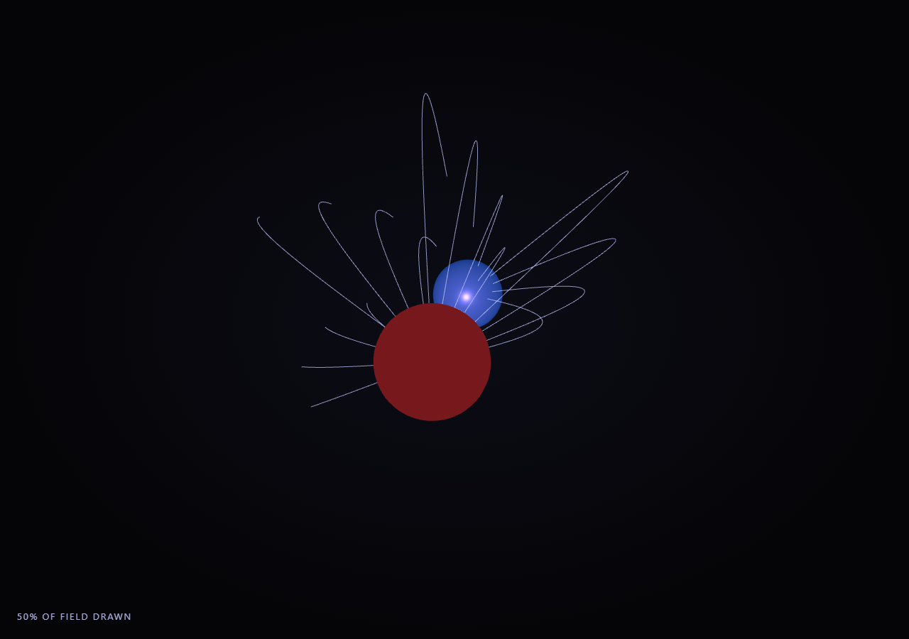
The Three.js Scroll Magnetic Field Lines snippet renders two glowing pole spheres — red for north, blue for south — connected by dozens of curved field-line arcs that draw themselves progressively, one after another, as the visitor scrolls through a pinned stage, evoking the classic iron-filings diagram of a bar magnet's field, swept around in 3D.
Parametric arcs, not a physics field solver
Rather than numerically integrating actual magnetic field equations, each field line is a hand-parameterized arc: it moves linearly along the pole axis from north to south (axisZ), while bulging outward perpendicular to that axis by sin(u * PI) * bow, where u is the 0-1 position along the line and bow varies per line. Rotating that bulge direction by a different angle for each of the 26 lines sweeps the classic 2D bar-magnet field-line silhouette all the way around the pole axis into a full 3D field pattern — visually convincing without needing to solve Biot-Savart integrals.
One THREE.Line per field line, revealed via drawRange
Each field line's full set of sample points is computed once at startup via BufferGeometry.setFromPoints, then rendered as a THREE.Line. The "stroke draw" reveal effect — each line appearing to trace itself from pole to pole — comes entirely from geometry.setDrawRange(0, count): setting count to a small number renders only the first few points (a short stub near the north pole), and increasing it toward the full point count reveals progressively more of the line's length, with no shader or masking trick required. This is the same drawRange revealing technique used for the path animation in scroll SVG path draw, applied here to a 3D curve instead of a flat SVG path.
Staggered per-line reveal windows for a natural draw-in sequence
Just like the panel stagger in origami crane unfold, each field line remaps the shared scrubbed eased progress into its own local 0-1 window via (eased - start) / span, with start values spread across most of the scroll range by line index. This means lines begin drawing themselves in sequence rather than all growing simultaneously, producing a much more organic "the field is forming" feel than a single uniform reveal would.
Reversible because drawRange is a pure function of progress
Every line's draw count is recomputed fresh from its local eased window every frame — nothing is accumulated frame to frame. Scrolling back up decreases the shared progress value, every line's local window value drops back toward zero, and setDrawRange shrinks each line back toward its stub near the north pole in the same staggered order, reversed.
Orbiting camera reveals the full 3D structure
Because all 26 field lines are swept around the pole axis at different angles, a single static camera view would flatten much of that structure. The camera continuously orbits around the pole axis throughout the whole scroll range, so the viewer sees the field lines' 3D arrangement from constantly shifting angles rather than a single flat silhouette.
Build with AI
Build, Understand, Optimize, and Extend It With AI
You do not need to reverse-engineer how dozens of curved field lines draw themselves in sequence between two magnetic poles. Paste this snippet's HTML, CSS, and JS into an AI assistant like Claude and ask it to explain how BufferGeometry's setDrawRange produces a stroke-draw reveal with no shader, or how the per-line staggered window formula creates a sequential formation effect. The same assistant can help you extend it — ask it to add small glowing particles that travel along each fully-drawn line from pole to pole, vary line color by field strength (denser near the poles), or add a second pair of poles for a more complex multi-magnet field pattern. Treat the code as a conversation starter, not a finished artifact.
Prompt to recreate it
Copy this into your AI assistant of choice to build the effect from scratch, or as a jumping-off point for your own variant:
Build a "scroll-scrubbed magnetic field lines" effect in plain HTML, CSS, and JavaScript using Three.js, GSAP, and GSAP's ScrollTrigger plugin, all loaded from a CDN (no bundler, no build step).

Requirements:
- A pinned section containing a full-size canvas, with a WebGLRenderer and PerspectiveCamera sized to the canvas element (not window.innerWidth/innerHeight) and updated on window resize including aspect ratio.
- Create two glowing pole spheres (a red "north" and a blue "south") positioned a fixed distance apart along one axis, each paired with a matching colored point light and an emissive MeshStandardMaterial.
- Generate roughly two dozen field lines once at startup: for each line, sample points along a parameter from 0 to 1 where the point's position lerps linearly along the pole axis while bulging outward perpendicular to that axis by a sine curve (peaking at the midpoint), with the bulge direction rotated by a different angle per line so the full set sweeps around the axis in 3D. Build each line's geometry via BufferGeometry.setFromPoints and render it as a THREE.Line.
- Set every line's initial geometry.setDrawRange(0, 0) so no lines are visible at rest.
- Register a GSAP tween on a ScrollTrigger targeting the pinned section, with pin: true, start at top top, a numeric scrub, and a multi-hundred-percent end, animating a single plain progress value from 0 to 1 with linear easing.
- Every animation frame, apply smoothstep easing to the scrubbed progress, then for each line remap that eased progress into its own local 0-1 window via a per-line start offset (spread across most of the scroll range based on line index) and a shared span, clamp it, and set that line's geometry.setDrawRange(0, localWindow * totalPointCount) so lines visibly draw themselves in a staggered sequence from the north pole toward the south pole.
- Continuously orbit the camera around the pole axis throughout the scroll range so the 3D arrangement of swept field lines is visible from shifting angles rather than one flat silhouette.
- Confirm scrolling back up reverses the entire reveal smoothly: each line's drawn length shrinks back toward its starting stub in the same staggered order, reversed, since draw range is a pure function of the shared progress value with no accumulated state.
Want to tighten it up first? Run this prompt through the AI Prompt Studio to score it across 8 quality dimensions, catch anti-patterns, and tune the wording for Claude, ChatGPT, or Gemini before you paste it in.
Source Code
<section class="mfl-stage" id="mflStage">
  <div class="mfl-intro-overlay"><p>Scroll ↓ to draw the magnetic field lines between the poles</p></div>
  <canvas id="mflCanvas"></canvas>
  <div class="mfl-hud"><span id="mflPct">0</span>% of field drawn</div>
</section>
<section class="mfl-bottom"><p>The full magnetic field, arcing from pole to pole.</p></section>*{box-sizing:border-box;margin:0;padding:0}
html,body{background:#050508;color:#fff;font-family:system-ui,-apple-system,sans-serif}
.mfl-bottom{min-height:70vh;display:flex;justify-content:center;align-items:center;color:#9aa0c9;font-size:15px;letter-spacing:.08em;text-transform:uppercase;text-align:center;padding:0 24px}
.mfl-stage{height:100vh;position:relative;overflow:hidden;background:radial-gradient(ellipse at center,#0c0c16 0%,#050508 70%)}
.mfl-intro-overlay{position:absolute;inset:0;display:flex;align-items:center;justify-content:center;text-align:center;padding:24px;pointer-events:none;z-index:5;color:#9aa0c9;font-size:15px;letter-spacing:.08em;text-transform:uppercase;transition:opacity .4s ease;}
#mflCanvas{display:block;width:100%;height:100%}
.mfl-hud{position:absolute;left:24px;bottom:24px;font-variant-numeric:tabular-nums;font-size:13px;letter-spacing:.14em;color:#c9cfff;text-transform:uppercase;opacity:.85}const canvas = document.getElementById('mflCanvas');
const pctEl = document.getElementById('mflPct');
const renderer = new THREE.WebGLRenderer({ canvas, antialias: true, alpha: true });
renderer.setPixelRatio(Math.min(window.devicePixelRatio, 2));
const scene = new THREE.Scene();
const camera = new THREE.PerspectiveCamera(50, 1, 0.1, 200);
camera.position.set(0, 3, 17);
camera.lookAt(0, 0, 0);
scene.add(new THREE.AmbientLight(0x2a2a44, 1.0));
const NORTH = new THREE.Vector3(0, 0, 4.5);
const SOUTH = new THREE.Vector3(0, 0, -4.5);
const poleGeo = new THREE.SphereGeometry(1.1, 32, 32);
const northMat = new THREE.MeshStandardMaterial({ color: 0xff4d4d, emissive: 0x5a0f0f, roughness: 0.4, metalness: 0.3 });
const southMat = new THREE.MeshStandardMaterial({ color: 0x4d8dff, emissive: 0x0f2a5a, roughness: 0.4, metalness: 0.3 });
const northPole = new THREE.Mesh(poleGeo, northMat);
northPole.position.copy(NORTH);
scene.add(northPole);
const southPole = new THREE.Mesh(poleGeo, southMat);
southPole.position.copy(SOUTH);
scene.add(southPole);
const northLight = new THREE.PointLight(0xff6666, 1.2, 30);
northLight.position.copy(NORTH);
scene.add(northLight);
const southLight = new THREE.PointLight(0x6699ff, 1.2, 30);
southLight.position.copy(SOUTH);
scene.add(southLight);
// Field lines: parametric arcs from north to south pole, varying in bow-out
// radius and rotation angle around the pole axis to fill out a 3D field
// pattern (like classic bar-magnet field-line diagrams, swept around in 3D).
const LINE_COUNT = 26;
const SEGMENTS = 48;
const lineMat = new THREE.LineBasicMaterial({ color: 0xbfc6ff, transparent: true, opacity: 0.75 });
const lineDefs = [];
for (let i = 0; i < LINE_COUNT; i++) {
const angle = (i / LINE_COUNT) * Math.PI * 2;
const bow = 2.2 + (i % 4) * 1.1;
const points = [];
for (let s = 0; s <= SEGMENTS; s++) {
const u = s / SEGMENTS; // 0 at north, 1 at south
// Parametric bulge: lerp north->south on the axis, with a sine bulge in
// the perpendicular plane rotated by the line's angle around the axis.
const axisZ = NORTH.z + (SOUTH.z - NORTH.z) * u;
const bulge = Math.sin(u * Math.PI) * bow;
const x = Math.cos(angle) * bulge;
const y = Math.sin(angle) * bulge;
points.push(new THREE.Vector3(x, y, axisZ));
}
const geo = new THREE.BufferGeometry().setFromPoints(points);
geo.setDrawRange(0, 0);
const line = new THREE.Line(geo, lineMat);
scene.add(line);
// Stagger each line's own reveal window across the overall scroll range so
// lines draw themselves in sequence rather than all at once.
const start = (i / LINE_COUNT) * 0.7;
lineDefs.push({ line, geo, totalPoints: SEGMENTS + 1, start, span: 0.4 });
}
const introEl = document.querySelector('.mfl-intro-overlay');
gsap.registerPlugin(ScrollTrigger);
const form = { t: 0 };
gsap.to(form, {
t: 1,
ease: 'none',
scrollTrigger: {
trigger: '#mflStage',
start: 'top top',
end: '+=450%',
scrub: 0.6,
pin: true,
},
});
function resize() {
const w = canvas.clientWidth, h = canvas.clientHeight;
renderer.setSize(w, h, false);
camera.aspect = w / h;
camera.updateProjectionMatrix();
}
let spin = 0;
function animate() {
requestAnimationFrame(animate);
if (introEl) introEl.style.opacity = (form.t > 0.03) ? '0' : '1';
const t = form.t;
const eased = t * t * (3 - 2 * t);
for (let i = 0; i < lineDefs.length; i++) {
const d = lineDefs[i];
let local = (eased - d.start) / d.span;
local = Math.max(0, Math.min(1, local));
const drawCount = Math.floor(local * d.totalPoints);
d.geo.setDrawRange(0, drawCount);
}
spin += 0.0016;
camera.position.set(Math.sin(spin) * 17, 3 + Math.sin(spin * 0.4) * 1.5, Math.cos(spin) * 17);
camera.lookAt(0, 0, 0);
pctEl.textContent = Math.round(eased * 100);
renderer.render(scene, camera);
}
resize();
window.addEventListener('resize', resize);
animate();Step by step
How to Use
- 1Load all three CDN scriptsAdd three.min.js, gsap.min.js, and ScrollTrigger.min.js from the CDN panel, in that order.
- 2Paste HTML, CSS, and JSTwo glowing pole spheres appear with no visible field lines yet, inside a pinned 3D stage with a live "% of field drawn" read-out.
- 3Scroll downField lines draw themselves from the north pole toward the south pole in a staggered sequence, while the camera orbits.
- 4Scroll back upField lines shrink back toward the north pole in the same staggered order, reversed, since drawRange is a pure function of progress.
- 5Retune the fieldChange LINE_COUNT for a denser or sparser field, or the bow formula for tighter or wider arcs.
- 6Adjust the pacingChange the ScrollTrigger end value (+=450%) or each line's start/span window to retime the staggered draw-in.
Real-world uses
Common Use Cases
Got questions?
Frequently Asked Questions
No. Each line is a hand-parameterized arc — linear travel along the pole axis combined with a sine-shaped bulge perpendicular to it — chosen because it visually resembles the classic bar-magnet field-line pattern seen in iron-filings diagrams. It is a deliberate, cheap approximation rather than a numerical solution to Biot-Savart or Maxwell's equations, which would be unnecessary computational cost for a decorative visualization.
Every field line's full set of sample points is computed once and stored in a THREE.BufferGeometry. THREE.Line renders only the vertex range specified by geometry.setDrawRange(start, count) — by animating count from 0 up to the line's total point count, the line visibly grows from its first point (near the north pole) to its last (near the south pole), entirely through this built-in draw-range mechanism with no shader or clipping-plane trick required.
Every line remaps the single shared scrubbed progress value into its own local 0-1 window via (eased - start) / span, where start is spread across roughly the first 70% of the scroll range based on the line's index. This means lines begin their draw-in at different scroll positions, producing a sequential, organic-feeling formation of the field rather than all 26 lines growing in perfect lockstep.
Yes. Each line's draw count is recomputed fresh every frame purely from its local eased window value, with no state carried between frames. Scrolling up decreases the shared progress value, every line's local window value drops back toward zero, and setDrawRange shrinks each line back toward its starting stub in the same staggered order, reversed.
Yes. Click JSX for a React component, Vue for a Vue 3 SFC, Angular for a standalone component, or Tailwind for a React + Tailwind version. Build the pole meshes, field-line geometries, and GSAP ScrollTrigger inside a mount effect keyed to a canvas ref, and on unmount kill the ScrollTrigger instance, dispose geometries/materials, and call renderer.dispose().