You Might Also Like
Learn Coding Visually
Learn to code with interactive, live-preview playgrounds — HTML, CSS, JavaScript, React & more.
 HTML Playground42 lessons · Click-based · Live preview
 CSS PlaygroundLearn CSS with a live editor
 JavaScript Playground60 lessons · DOM · Async · Canvas
 React PlaygroundLearn React with a live code editor
 GSAP PlaygroundLearn GSAP animation interactively
 SVG Playground44 lessons · shapes · paths · animation
 SCSS Playground45 lessons · Sass modules · tokens
 Tailwind PlaygroundLearn Tailwind CSS with a live editor
 Bootstrap 5 Playground50 lessons · live preview
Logic Gate Puzzle Game — Free HTML CSS JS Snippet
Logic Gate Puzzle Game · Games · Plain HTML, CSS & JS · Live preview
What's included
Features
About this UI Snippet
Logic Gate Puzzle Game — Full Truth-Table Grading, Live Circuit State & Behavioural Equivalence
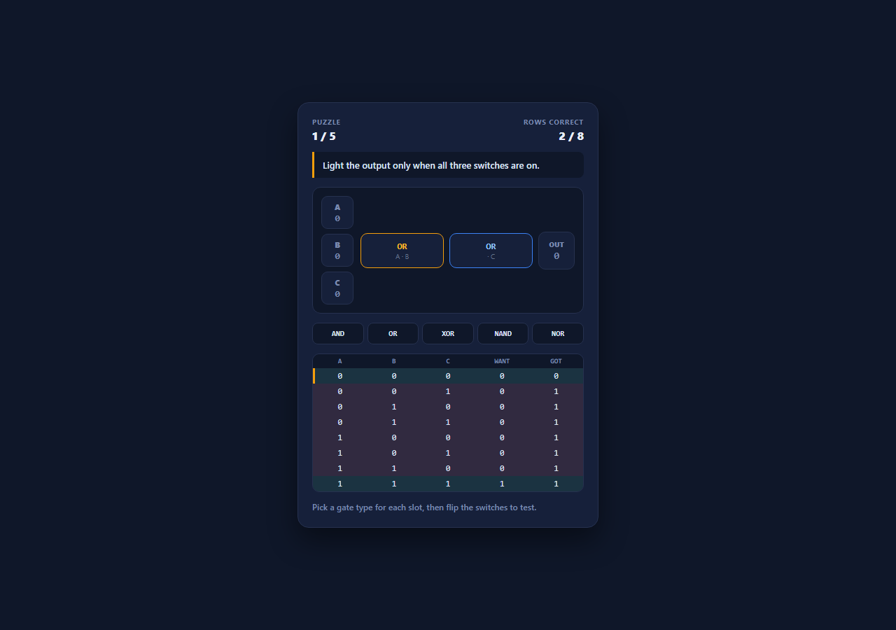
Boolean logic is the substrate under every conditional anyone ever writes, and it clicks the moment you can flip a switch and watch a wire light up. This snippet is a playable circuit puzzle: a fixed two-gate circuit wired as gate1(gate0(A, B), C), five gate types to choose from, three input switches, and a target described in plain English. The player picks gates until the circuit's behaviour matches the target across every possible input — not just the case currently on screen.
Graded on the whole truth table, not the visible state
The critical design decision is that the win condition evaluates all eight input combinations, not the three switches as they currently stand. ROWS is generated by extracting bits from the numbers 0-7 with (i >> 2) & 1, (i >> 1) & 1 and i & 1, which produces the canonical truth-table ordering without a hand-written table. Every render re-evaluates the circuit for all eight rows and shows want versus got side by side, so a circuit that happens to be right for the switches you are looking at but wrong elsewhere is visibly, specifically wrong — which is exactly the bug that hides in real conditional logic.
Behavioural equivalence, not a stored answer
Levels define their target as a JavaScript function of (a, b, c) rather than as a required pair of gate names. Any gate combination producing the same output column clears the puzzle, so a player who reaches the answer by a route the author did not anticipate is rewarded — and several of these targets genuinely have more than one solution, since NAND and NOR can substitute for combinations of the others. Grading behaviour rather than structure is what makes the game teach Boolean equivalence instead of gate trivia.
Gates as a lookup table of pure functions
GATES is an object mapping each name to a two-argument function built on JavaScript's bitwise operators — a & b, a | b, a ^ b, and the negated forms for NAND and NOR. The picker buttons are generated from Object.keys(GATES), so adding XNOR means adding one entry and nothing else: the picker, the evaluation, and the truth table all pick it up automatically. Using bitwise operators on 0/1 integers rather than booleans keeps the whole model in the same representation the truth table displays.
Live state shown on the wires
evaluate() returns both the intermediate value out of the first gate and the final output, which lets the UI light each gate independently — so a player flipping switches can see where a signal dies. That intermediate readout is the difference between a puzzle and an explanation: when the output is dark, you can tell at a glance whether the first gate produced a 0 or the second gate consumed a 1 and produced nothing. The row of the truth table matching the current switch positions is marked, tying the interactive view and the exhaustive view together.
Puzzles that build toward parity
The five targets run from a three-way AND, through an OR feeding an AND, an XOR feeding an OR, a three-input parity check (output high when an odd number of inputs are on — the basis of parity bits and checksums), and finally a NAND-based condition. Parity is the one that repays study: it is the standard example of a function that cannot be expressed without XOR-like behaviour, and building it by hand is more convincing than reading that fact.
Build with AI
Build, Understand, Optimize, and Extend It With AI
Paste this snippet into an AI assistant like Claude and ask it to add a NAND-only mode where every slot is forced to NAND and the circuit grows to four or five gates — building AND, OR and XOR out of nothing but NAND is the classic demonstration of functional completeness, and it is genuinely satisfying to solve. Other extensions worth requesting: let the player add and remove gate slots so the circuit shape is part of the puzzle, add a fourth input with a sixteen-row truth table, add a score based on gate count so simpler solutions win, or generate the plain-English goal automatically from the target function so new puzzles need only a Boolean expression.
Prompt to recreate it
Copy this into your AI assistant of choice to build the effect from scratch, or as a jumping-off point for your own variant:
Build a playable logic gate puzzle game in plain HTML, CSS, and JavaScript — no frameworks or libraries.

Requirements:
- A fixed two-gate circuit wired as gate1(gate0(A, B), C), with three input switches that toggle between 0 and 1 and an output indicator.
- A GATES lookup object mapping names (AND, OR, XOR, NAND, NOR) to two-argument pure functions built on bitwise operators, with the gate picker buttons generated from Object.keys(GATES) so adding a gate type requires only a new entry.
- Levels that define their target as a JavaScript function of (a, b, c) returning 0 or 1 — never as a required pair of gate names — so ANY behaviourally equivalent gate combination clears the puzzle.
- Generate the eight truth-table rows by bit extraction from the numbers 0-7 ((i >> 2) & 1, (i >> 1) & 1, i & 1) rather than hand-writing a table.
- Evaluate the circuit against ALL eight input combinations on every change and display want versus got per row, colouring each row. The puzzle clears only when all eight rows match — never merely when the current switch state looks right.
- Expose the intermediate value out of the first gate as well as the final output, and light each gate independently so a player can see where a signal dies. Highlight the truth-table row matching the current switch positions.
- Include at least five puzzles described in plain English, progressing to a three-input parity check (output high when an odd number of inputs are on), and report the solved expression in the success message.
Want to tighten it up first? Run this prompt through the AI Prompt Studio to score it across 8 quality dimensions, catch anti-patterns, and tune the wording for Claude, ChatGPT, or Gemini before you paste it in.
Step by step
How to Use
- 1Read the target in plain EnglishEach puzzle describes the behaviour you have to build — "light the output when an odd number of switches are on" — rather than naming the gates, so you have to reason about the logic instead of following instructions.
- 2Pick a gate for each slotThe five buttons set the gate type for the currently highlighted slot, then move the highlight to the other slot automatically. Clicking a gate in the circuit selects it directly if you want to change just one.
- 3Flip the switches to testA, B and C toggle between 0 and 1. Both gates light independently, so you can see whether a dark output is because the first gate produced 0 or the second consumed a 1 and produced nothing.
- 4Watch the full truth tableAll eight input combinations are evaluated on every change and shown as want versus got. A circuit that is right for the switches you are looking at but wrong elsewhere shows exactly which rows disagree.
- 5Match all eight rows to solveThe puzzle clears when every row matches — not when the current switch state happens to look right. Any gate combination producing the correct output column is accepted, and several puzzles have more than one valid answer.
- 6Work up to the parity puzzleThe five targets progress from a three-way AND to a parity check that lights when an odd number of switches are on — the logic behind parity bits and simple checksums.
Real-world uses
Common Use Cases
Got questions?
Frequently Asked Questions
Every possible input. All eight combinations of A, B and C are evaluated on every change and shown as want versus got, and the puzzle only clears when all eight rows match. A circuit that happens to be correct for the current switch positions but wrong elsewhere is explicitly shown as wrong — which is the same failure mode as a conditional tested on only one case.
Not necessarily. Levels define their target as a function of (a, b, c), and any gate combination producing the same output column is accepted. Because NAND and NOR are functionally complete, several puzzles have more than one valid answer — grading behaviour rather than structure is what makes the game teach Boolean equivalence.
By extracting bits from the numbers 0 through 7: (i >> 2) & 1 for A, (i >> 1) & 1 for B, and i & 1 for C. That produces the canonical truth-table ordering automatically, with no hand-written table to get out of sync, and the same technique scales to four or more inputs by widening the loop.
Add an entry to the GATES object — for example XNOR as (a, b) => (a ^ b) ? 0 : 1 — and the picker, the evaluation and the truth table all pick it up, since the buttons are generated from Object.keys(GATES). For a new puzzle, push an object onto LEVELS with a plain-English goal and a want function of (a, b, c) returning 0 or 1.
Yes, and it maps unusually well because evaluate() and every gate are pure functions. Hold the two gate choices, the three input bits and the active slot in component state; derive the live wire values, the output, and the entire truth table during render rather than mutating classes. The only side effect is the advance timeout after a solve, which should be cleared on unmount (useEffect cleanup, onUnmounted, ngOnDestroy) so a level change cannot fire after the component is gone.